Modular Jack Wiring

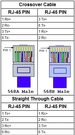
EIA/TIA 568A & 568B Standard

There are four basic modular jack styles. The 8-position and 8-position keyed modular jacks are commonly and incorrectly referred to as RJ45 and keyed RJ45 (respectively). The 6-position modular jack is commonly referred to as RJ11. Using these terms can sometimes lead to confusion since the RJ designations actually refer to very specific wiring configurations called Universal Service Ordering Codes (USOC).

The designation ‘RJ’ means Registered Jack. Each of these 3 basic jack styles can be wired for different RJ configurations. For example, the 6-position jack can be wired as an RJ11C (1-pair), RJ14C (2-pair), or RJ25C (3-pair) configuration. An 8-position jack can be wired for configurations such as RJ61C (4-pair) and RJ48C. The keyed 8-position jack can be wired for RJ45S, RJ46S, and RJ47S.

The fourth modular jack style is a modified version of the 6-position jack (modified modular jack or MMJ). It was designed by Digital Equipment Corporation® (DEC) along with the modified modular plug (MMP) to eliminate the possibility of connecting DEC data equipment to voice lines and vice versa.

Common Outlet Configurations:

Two wiring schemes have been adopted by the ‘568-A standard. They are nearly identical except that pairs two and three are reversed. T568A is the preferred scheme because it is compatible with 1 or 2-pair USOC systems. Either configuration can be used for Integrated Services Digital Network (ISDN) and high speed data applications.

USOC wiring is available for 1-, 2-, 3-, or 4-pair systems. Pair 1 occupies the center conductors, pair 2 occupies the next two contacts out, etc. One advantage to this scheme is that a 6-position plug configured with 1 or 2 pairs can be inserted into an 8-position jack and maintain pair continuity. A note of warning though, pins 1 and 8 on the jack may become damaged from this practice. A disadvantage is the poor transmission performance associated with this type of pair sequence.

Use a straight thru cable assembly,568B on both ends when connecting Hub to Xcvr or NIC Card. When connecting hub to hub, Xcvr to Xcvr, or NIC to NIC, the wires must crossover at the opposite end of the cable assembly,use the 568B on one end, 568A on the other end.

A crossover cable is required when connecting a Hub to a Hub, or a Transceiver to Transceiver, or NIC to NIC card, or Transceiver to NIC card. When connecting a Hub to a transceiver or NIC card, a straight through cable is always used. Please Note: Some products are equipped with internal switches that can internally cross the twisted pairs.

10BASE-T Crossover Wiring

For a single segment connecting only two computers you can provide the signal crossover by building a crossover cable, with the transmit pins on the eight-pin plug at one end of the cable wired to the receive data pins on the eight-pin plug at the other end of the crossover cable and vice versa.